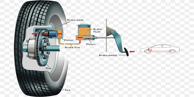
Automobile the hydraulic system

The hydraulic system described in this chapter does not represent an actual system used in any particular make of gearbox; instead, it illustrates the basic principles of automatic control by using a much simplified system. From this base system, you should be able to comprehend the construction and operation of a modern unit.
Pump
Normally, an internal–external gear pump is used (refer to the engine section on page 111 for information on the oil pump operation). This pump is driven at engine speed by tangs formed on the torque converter casing. The fl uid is drawn from the reservoir and passed to the pump through a fi ne screen-type filter, so as to remove any small dirt particles.
Since most modern automatic gearboxes have only one pump at the input, it is not possible to tow start the engine. This is because the engine and pump will be stationary, so pressure will not be generated in the system to activate any clutch and brake – neutral will result.
Primary regulator
Fluid released from the valve is passed back to the inlet side of the pump instead of being discharged into the reservoir. This action saves energy that would be used if the fluid had to be drawn through the fi ne-mesh filter screen.
Secondary regulator
Line pressure is too great for the converter, so the secondary regulator acts as a pressure reducer. A portion of the fluid returning from the converter passes either to oil cooler or to a line that provides low-pressure lubrication of the gearbox.
Manual valve
Under the control of the driver, this valve distributes the fluid to the various valves, clutches and brakes. It should be noted that wear on the forward clutch is minimal because, unlike the rear clutch, the application of the forward clutch is only carried out when the vehicle is stationary.
Speed and load sensing
Gear changes must be made when a predetermined road speed is reached, so some form of sensor is necessary to ‘tell’ the gearbox when to change the gear. Automatic gearboxes use one of the following to determine the speed of the output shaft
- Mechanical governor
- Hydraulic governor
- Electronic speed sensor
The speed sensor must work in conjunction with a shift valve (change valve); the duty of this valve is to direct the fluid to the clutches and servos so as to change the gear when a suitable road speed is reached.
Mechanical governor
This centrifugal system consists of two bob-weights, which throw out against the resistance of spring as the speed of rotation increases. The governor is driven from the output shaft, and the movement of the bob-weights operates a hydraulic spool valve that directly controls the gear changes. Today, very few gearboxes use this system of speed sensing.
Hydraulic governor
This type was developed from the mechanical governor. It uses a spool valve, sensitive to a centrifugal effect given by its rotation, to generate a fluid pressure that increases with speed.
Electronic speed sensor
An indication of the road speed is needed for many electronic systems used on modern vehicles. This data is provided by some form of magnetic sensor fitted close to the output shaft of the gearbox. Signals from the sensor are passed to an ECU for processing so that the data can be used for a particular electronic system such as gearbox control.
Last word
When the pedal is fully depressed, the cam moves the kick down valve to the right, causing a pressure increase in the throttle line.


