Automobile Hydraulic control of actuators
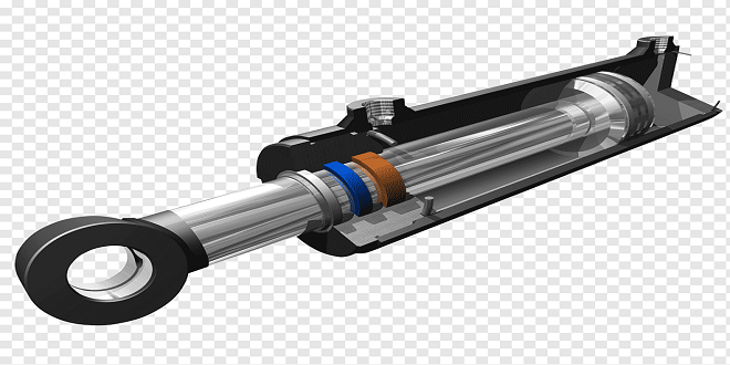
The clutches and brake bands of most automatic gearboxes are operated by hydraulic means. A pump, driven at engine speed from the torque converter, generates the fluid pressure; this pressure should be sufficiently high to lock the clutch plates or brake drum, but not so high as to waste energy. The distribution of fluid to the clutches and brakes is by means of a control valve, called a manual valve, linked to the driver’s selector lever.
Valve operation
Although many valves are used in automatic gearboxes, the basic principle of operation of each valve is the same. At this stage, the construction and operation of some of the valves is considered.
Regulator valves (relief valves)
The main purpose of this type of valve is to limit the hydraulic line pressure to a given maximum.
Ball and plunger-type relief valves
Ball and plunger-type valves are similar to those used on engines. When the pressure acting on the valve produces a thrust greater than the force exerted by the spring, then the valve lifts and so prevents any further increase in the pressure. The operation is based on the relationship:
Thrust = Pressure × Area
Spool-type relief valves
Simple spool valves are similar to the plunger-type except that they are waisted (reduced in the area at the center) to control the fluid flow. When pressure is sufficient to lift the valve, a port is uncovered. Fluid will then flow to the waisted part of the valve from where it is either returned to the reservoir or passed to a line that acts on another part of the system. Differential spool valves have two spools ‘plungers’ of a different diameters similar.
As fluid pressure begins to build up, the spool will move to the right; this is because the effective area of B exposed to the fluid is larger than that of A. The actual movement of the spool is controlled by the spring strength. The spring is situated in a chamber that is vented to avoid a pressure build-up behind the valve. When the pressure reaches a set value dictated by the spring, the spool uncovers the port C; this spills out the fluid and prevents any further rise of pressure.
Pressure-sensitive control valves
The basic system for the automatic control of the gear changes must sense the speed of the road wheels. A hydraulic system of control uses a governor for this purpose. Mounted on the output shaft, the governor generates a fluid pressure that increases as the road speed rises. Control valves, connected to the governor fluid circuit, sense the pressure in this circuit. At the appropriate time, the valve operates and directs the fluid through the lines to engage the new gear
Last word
Any pressure given by the fluid at E will have no effect on the movement of the valve because the thrust tending to move the valve to the right will be balanced by an equal and opposite thrust acting on the other face. In many ways, this is similar to the action of the two springs.

